Welcome to the OBD2 CAN Bus Controller project page. This innovative project combines hardware design, embedded systems programming, and mobile application development to create a comprehensive automotive diagnostic and control system. The system enables real-time monitoring and control of vehicle systems through the OBD2 port using CAN bus communication.
Features
- Real-time Vehicle Diagnostics: Access comprehensive vehicle data including engine parameters, fuel consumption, and system status
- CAN Bus Communication: Direct interface with vehicle's CAN bus network for high-speed data exchange
- Wireless Control: Bluetooth Low Energy (BLE) communication between ESP32 and Android device
- Custom PCB Design: Compact, professional-grade printed circuit board optimized for automotive environments
- Android Application: Intuitive mobile interface for monitoring and controlling vehicle systems
- Data Logging: Record and analyze vehicle performance data over time
- Safety Features: Built-in protection against electrical damage and system overload
Key Functionality
The system provides automotive enthusiasts and technicians with:
- Vehicle Health Monitoring: Real-time access to engine diagnostics, fuel efficiency, and system performance
- Custom Command Interface: Send specific commands to vehicle systems for testing and control
- Data Visualization: Graphical representation of vehicle parameters and trends
- Remote Diagnostics: Perform vehicle diagnostics without physical access to the vehicle
- Performance Analysis: Track and analyze vehicle performance over time
Hardware Design
| Component | Description |
|---|---|
| ESP32-S3-WROOM-1 | Microcontroller with Wi-Fi and Bluetooth capabilities. |
| LM1117 Linear Regulator | Provides a stable 3.3V power supply. |
| MAX3051 3.3V CAN Transceiver | Facilitates communication over the CAN bus. |
| CAN bus ESD protection diode | Protects the CAN bus from electrostatic discharge. |
| Micro USB ESD protection | Protects the Micro USB port from electrostatic discharge. |
| OBD2 Connector | Connects to the vehicle's OBD2 port. |
| Micro USB B Connector | Provides a connection for power and data transfer. |
| Transistor BJT NPN 2N2222A | Used for switching and amplification. |
| Resistors, capacitors, diodes, etc. | Various passive components for circuit functionality. |
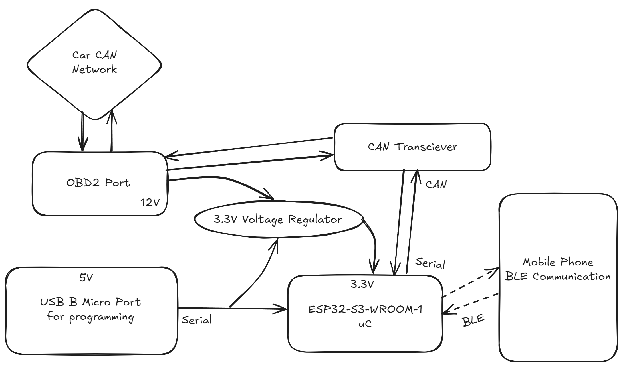
Block Diagram
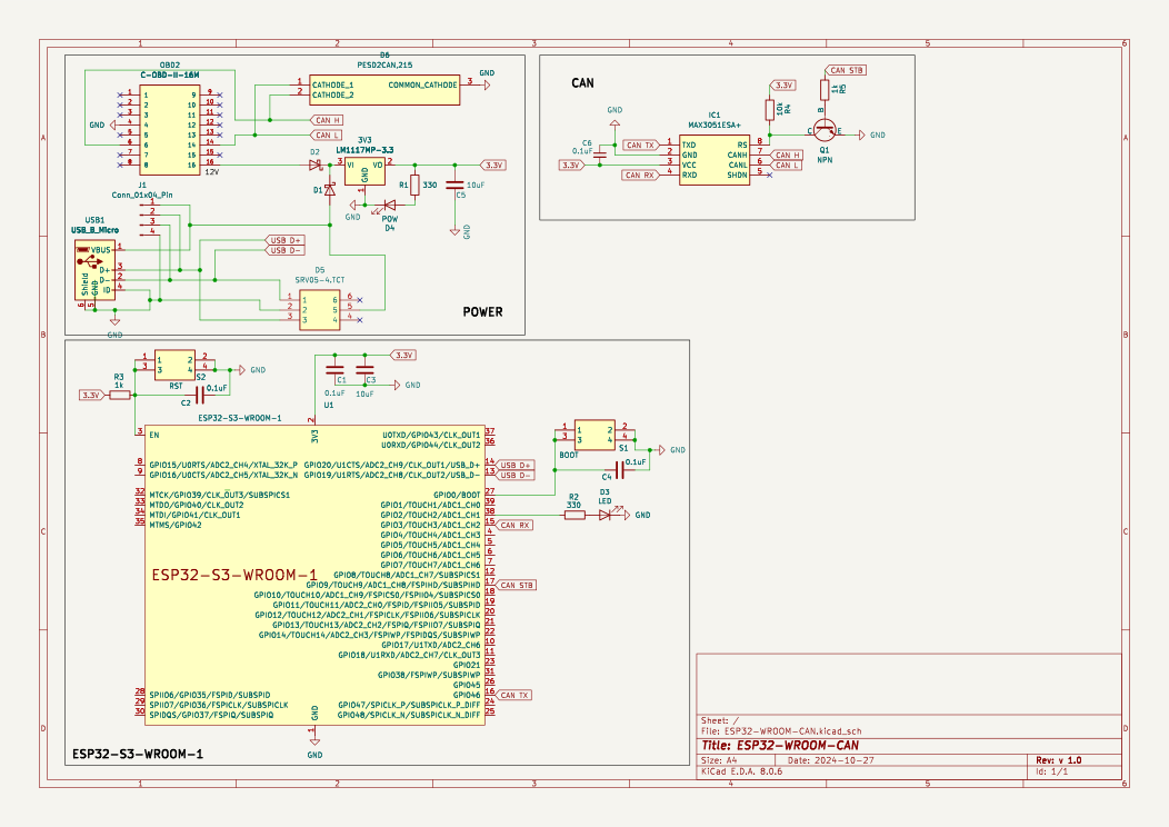
Schematic
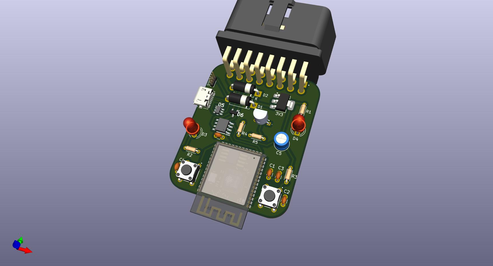
PCB
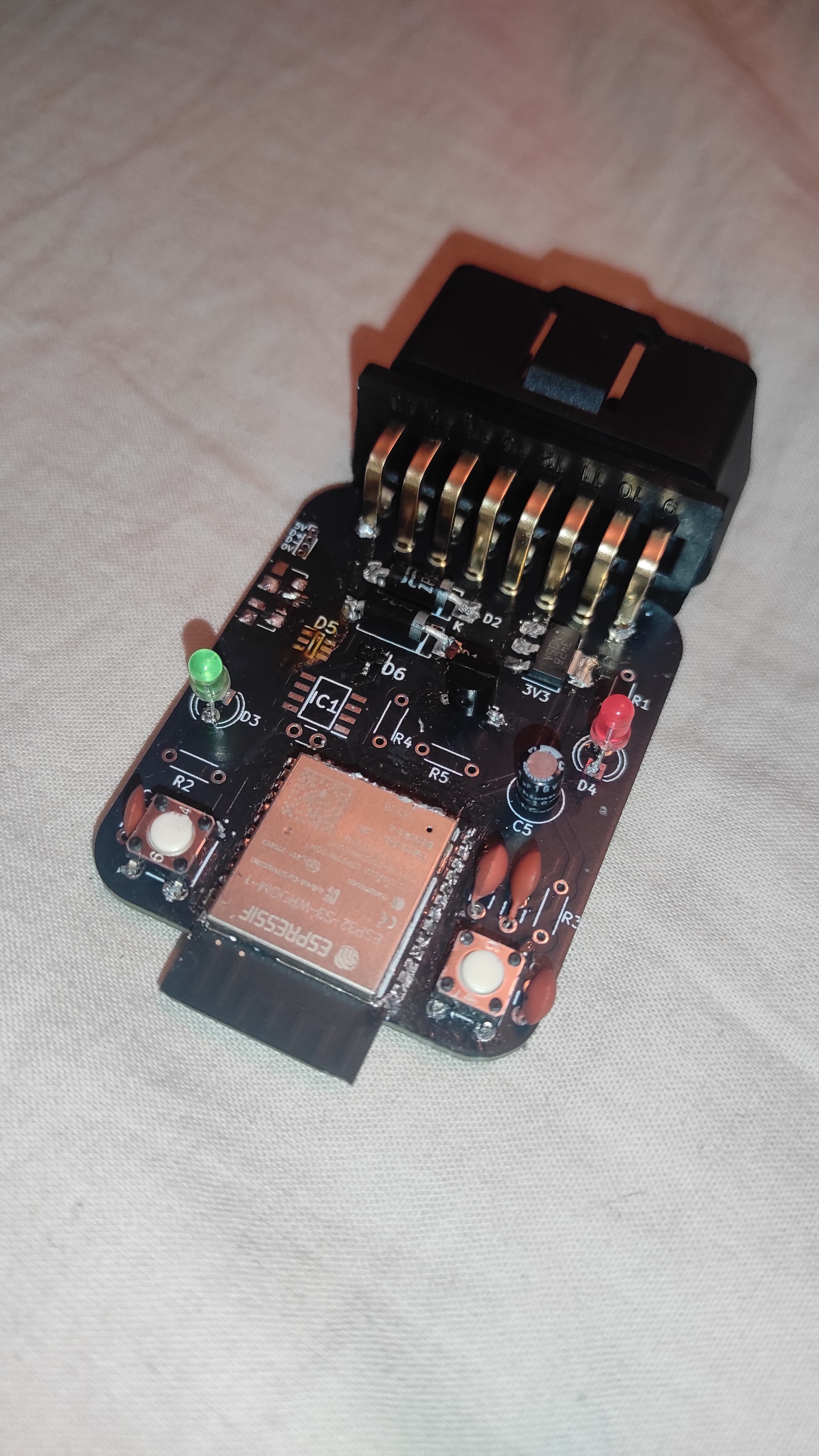
Milestone 2 Hardware Progress
Technologies Used
- ESP32-S3-WROOM-1: High-performance microcontroller with Wi-Fi and Bluetooth capabilities
- CAN Bus Protocol: Industry-standard automotive communication protocol
- Android Development: Native Android application with BLE communication
- PCB Design: Professional-grade circuit board design and manufacturing
- PlatformIO: Advanced embedded development environment
- C++ Programming: Low-level embedded systems programming
Project Impact
This project demonstrates advanced skills in embedded systems, automotive electronics, and mobile application development. The system provides a practical solution for automotive diagnostics and control, showcasing the integration of hardware design, embedded programming, and mobile development technologies.
Development Environment
- PlatformIO - Advanced embedded development platform
- VSCode - Integrated development environment
- KiCad - PCB design and schematic capture
- Android Studio - Android application development